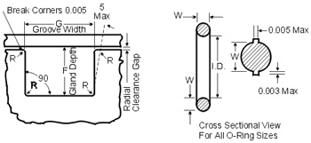
| O-Rings are one-piece molded objects made from elastometric seal with a circular cross-section. They are used to prevent fluid movement between mechanical parts by maintaining contact with the inner and outer walls enclosing the ring. The resiliency of the rubber provides a zero-pressure seal. When pressure is applied, the fluid forces the O-Rings across the groove and causes more deformation. This leads to the ring flow up to the fluid passage and seal it against leakage. O-Rings are an example of self-energize seals, meaning they relay pressure inside the container (or pipe) to give them the pressure necessary to form the seal. O-Rings are inserted into cavities called glands, and they are used in either axial or radial seal designs. An O-Ring is described by its inner diameter, its outer diameter, its material hardness (or durometer) and its material composition. Dimensions of O-Rings are given in ANSI/SAE AS568A. A seven-digit number is assigned to each ring to designate the ring size and their composition. The first three digits are standardized and they specify the ring size. However, different manufacturer use different system to specify the composition. For this reason, the ANSI/SAE AS568A only publishes the first three digits for dimension specification. When installed, an O-Ring compresses and deforms slightly into the free space within the grove to from a proper seal. The ring's cross-section is approximately 20 percent greater than the gland depth and the groove width is about 1.5 times larger than the ring's width. | |||||||||||||||||||||||||||||||||
 | |||||||||||||||||||||||||||||||||
Symbol Definitions | |||||||||||||||||||||||||||||||||
Parameters used in the discussion of O-Rings are defined in the following table:
| |||||||||||||||||||||||||||||||||
Radial Gland Symbol Definitions Parameters used in the discussion of glands for radial seals are defined in the following table:
| |||||||||||||||||||||||||||||||||
Design Guidelines Using the diametrical clearances given by the O-Rings' manufacturer usually provides the most effective and reliable sealing. They often provide information that can be used to estimate the gland depth required in O-Rings applications. This information is necessary for designing a system with a proper clearance gap so that the ring material will not extrude into the gap when subjected to pressure. The extruded ring material will quickly wear and fray, severely limiting the service life of the seal. Other factors, such as system pressure, ring compound and hardness, can affect the radial clearance used. There are number of ways to correct an extruding O-Rings application: | |||||||||||||||||||||||||||||||||
| |||||||||||||||||||||||||||||||||
| These modifications, however, have their drawbacks. For example, reducing system-operating pressure may affect the operational parameter of the system and harder O-Rings may result in higher friction and a greater tendency of the seal to leak at low pressure. In general, the ring's cross-section is about 20 percent great than the gland depth and the groove width is approximately 1.5 times the ring's cross sectional diameter if the its cross-section is larger than 1/16 in. The surface finish of the groove has a great impact on the performance of the seal. There are two things to consider for determining the surface finish roughness: | |||||||||||||||||||||||||||||||||
2. In the case of static seal, whether the seal is for a liquid system or a gaseous system. | |||||||||||||||||||||||||||||||||
The table below sums up the intended application with the proper surface finishes:
It is desirable to circumferentially stretch the O-Rings slightly so that it sits securely in the groove during assembly. This can be done by selecting an O-Ring with an internal diameter 2% to 3% smaller than the groove diameter. For Further Details Email us : sales@fitcoseals.com www.oringstore.com www.fitcoseals.com | |||||||||||||||||||||||||||||||||
Saturday, 21 July 2018
O-Rings Design Guidelines, Specifications - FITCO
Subscribe to:
Post Comments (Atom)
No comments:
Post a Comment